Stressed Skin
Project Details
| Date | January 2018 Elective, 2nd Year Summer Semester |
|---|---|
| Credits | Nitika Duggal Toan Thai Dinh David Ge Tobias Horrocks Carmelo Leuzzi Anthony Mollica Alexander Moss Zhusong Mei Xuan Huy Nguyen Hoang-Nguyen-Phan Liang Peng Ivana Seizova Paul Nicholas (CITA) Tim Schork (UTS) Dane Voorderhake (UTS) CITA (academic partner) CASA (Special Thanks) |
| Type | Advanced Digital Technology Exploration |
| Institution | University of Technology Sydney (UTS) |
| Applications | Rhino 5, Grasshopper, Adobe Photoshop, Adobe Illustrator, Adobe Premiere Pro |
Project Summary
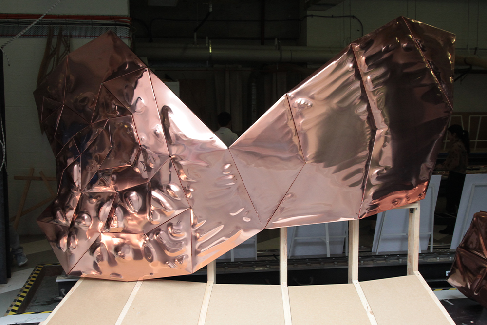
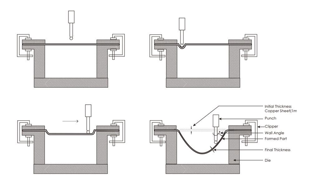
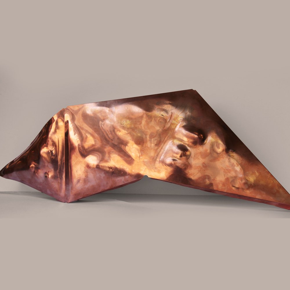
By incrementally forming thin sheet metal, one can enhance the structural integrity whilst keeping the structure lightweight. This methodology can be applied but not limited to ornamentation, structures, and skins. A 1:1 prototype was constructed out of copper within 2 weeks, as challenges such as seams in junction with the curvature were tackled, revealing a complex incrementally formed copper facade piece.
Tools + Toolpaths
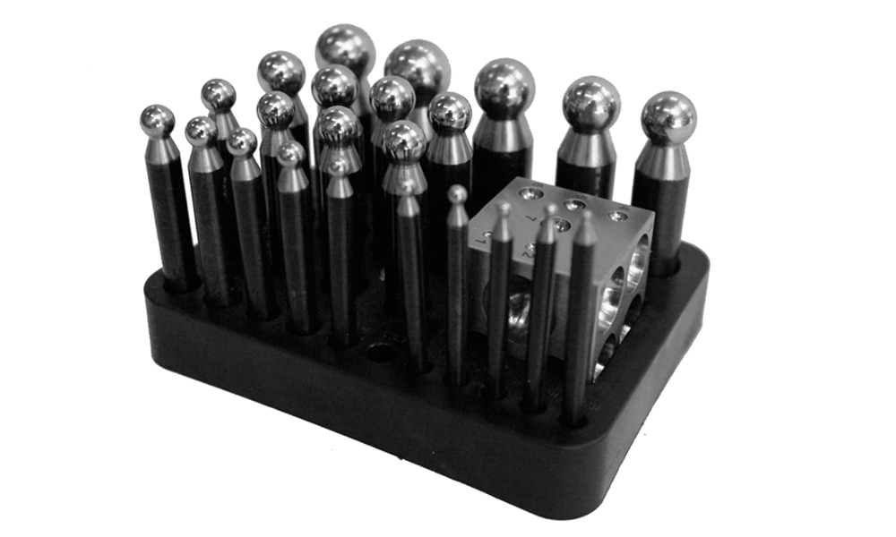
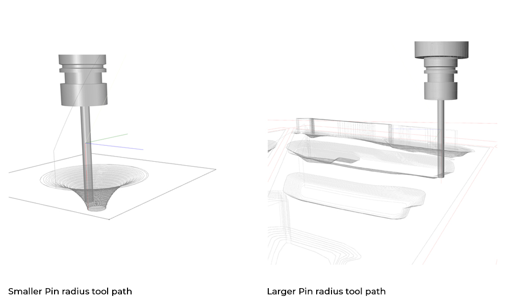
A ball tool bit pin would be attached to the Kuka Robot arm, I which could be used to incrementally apply pressure onto the copper sheets to generate the form desired. These paths in which the bit will follow is outlined by a grasshopper script, prior to the commencement of the procedure. Variables could be altered, such as the pin size, as well as the incremental depth, each giving rise to different characteristics. For instance, a larger bit and increment depth would provide shorter manufacturing durations, however, will make the toolpath lines more visible on the plate, as well as increases the chance of breakage mid production.
Forming Test
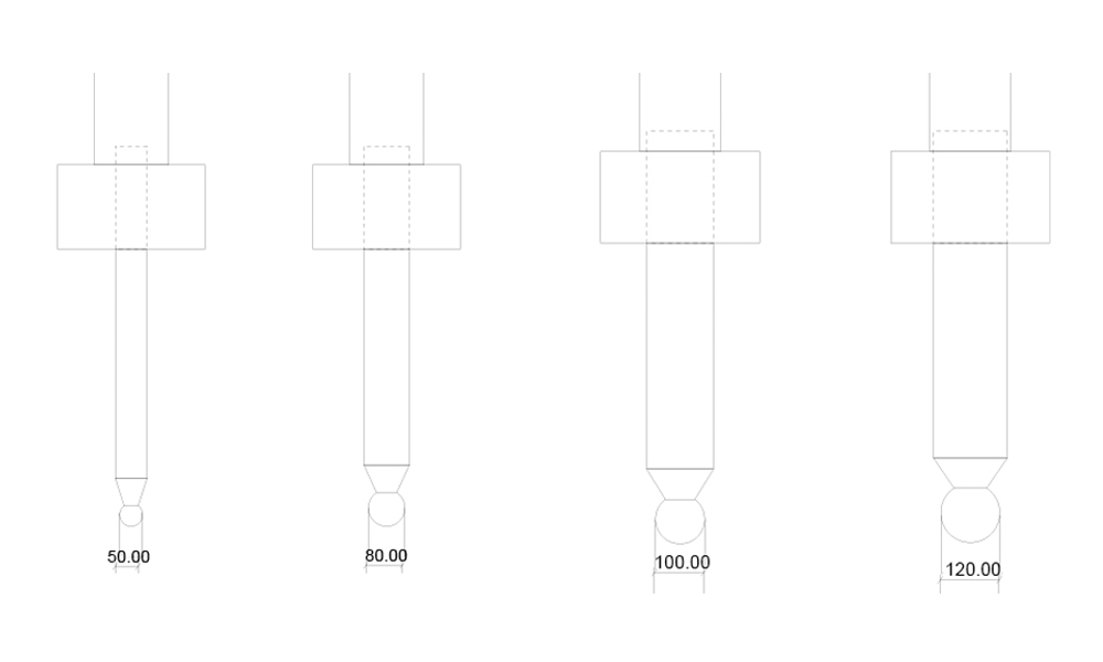
The primary goal of these tests was to observe how incrementally forming the copper would impact it's thickness, and how this relates to the possibility of the piece breaking. The 4 tests differ in tool bit size, step down depths, as well as different toolpath geometries, in aim to observe any likely circumstance we may come across in the final design.
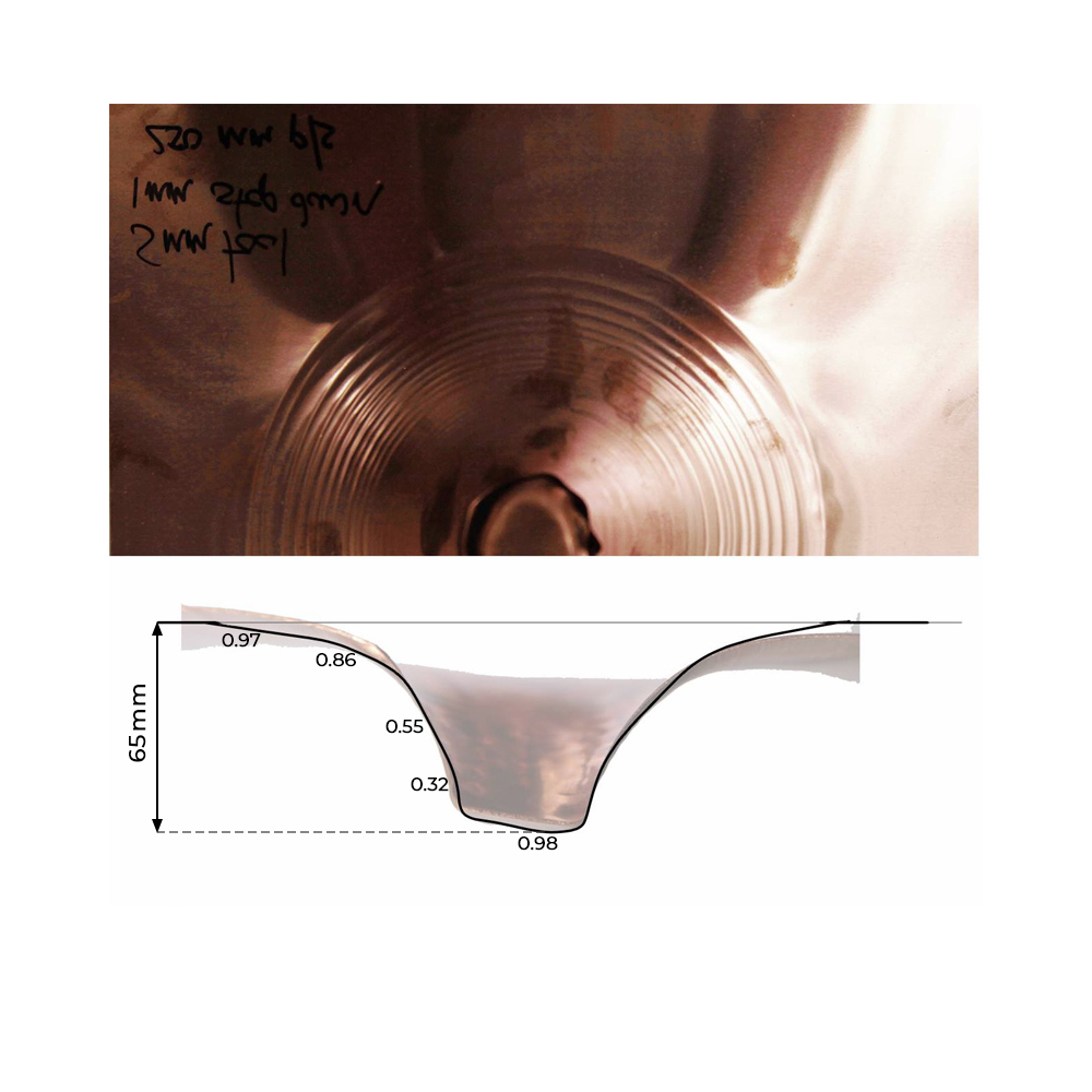
Test A
5mm tool
250mm p/sec
1mm step down
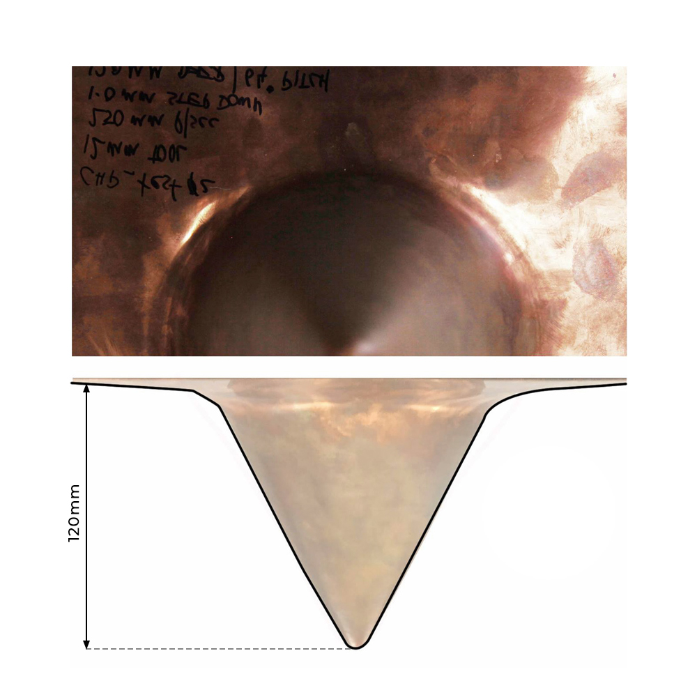
Test B
12mm tool
250mm p/sec
1mm step down
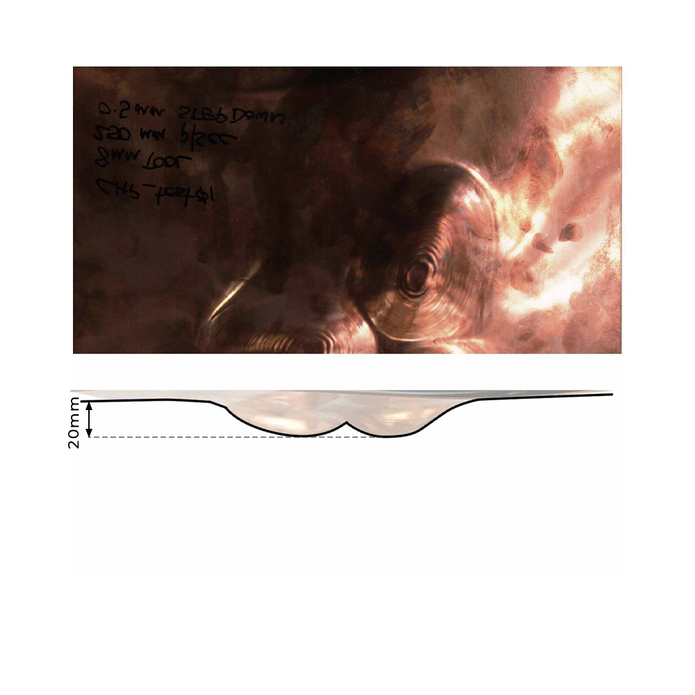
Test C
8mm tool
250mm p/sec
0.5mm step down
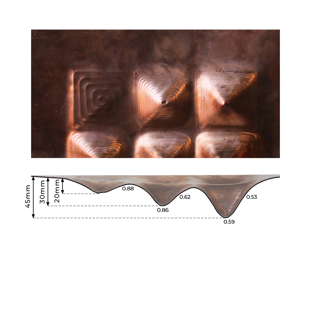
Test D
8mm tool
250mm p/sec
1mm step down
Accelerating Patina
The patina test was done to examine two factors for our facade. One was to see what would happen if the copper structure were to be exposed to water due to being outside, and the other was to see if we desired to deliberately have heavy patina as a surface finish. For control purposes, we prepared the solution in a beaker first, before applying it to the surface of these copper plates. It would be incredibly difficult to evenly distribute the solution across the plate due to surface tensions, thus meaning if we wanted to deliberately corrode the structure, we must submerge the entire project in the solution, an action we cannot do due to our resources. Thus, we decided to not have a patinated copper structure.
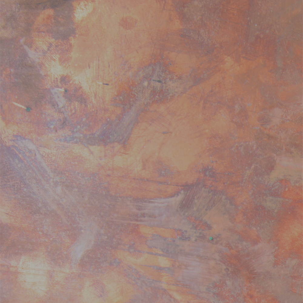
Original Copper Plate
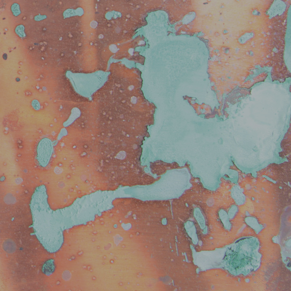
1 x (HCl) : 2 x (H20)
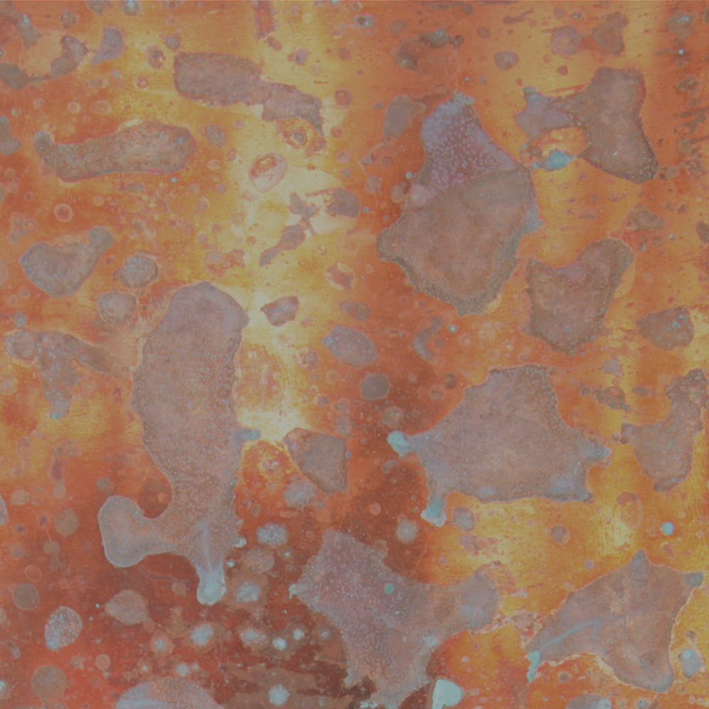
H20 Only
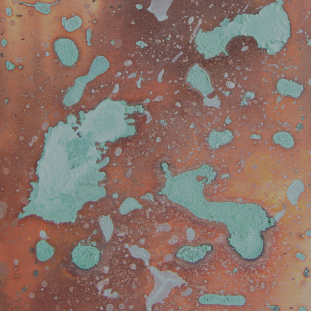
1 x (HCl) : 1 x (H20)
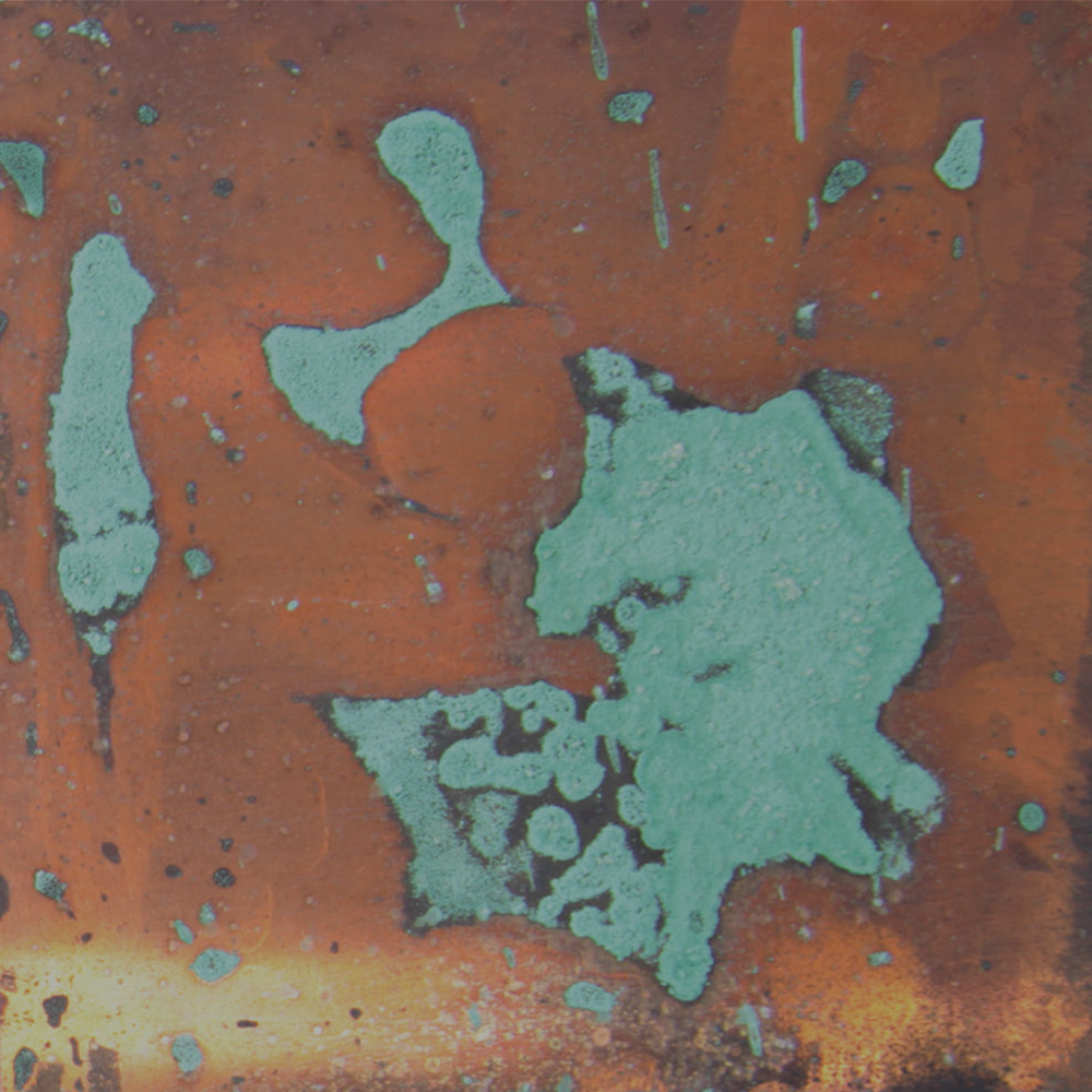
HCl Only
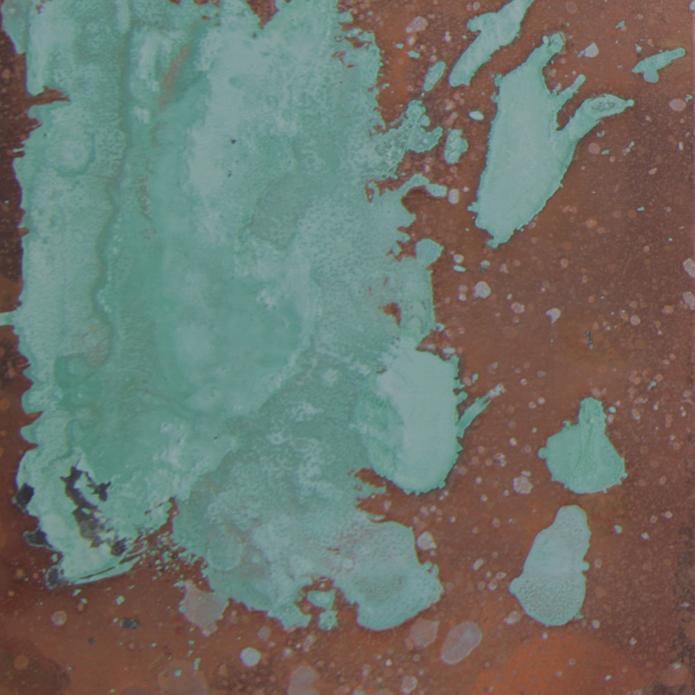
2 x (HCl) : 1 x (H20)
Standing Seam Test
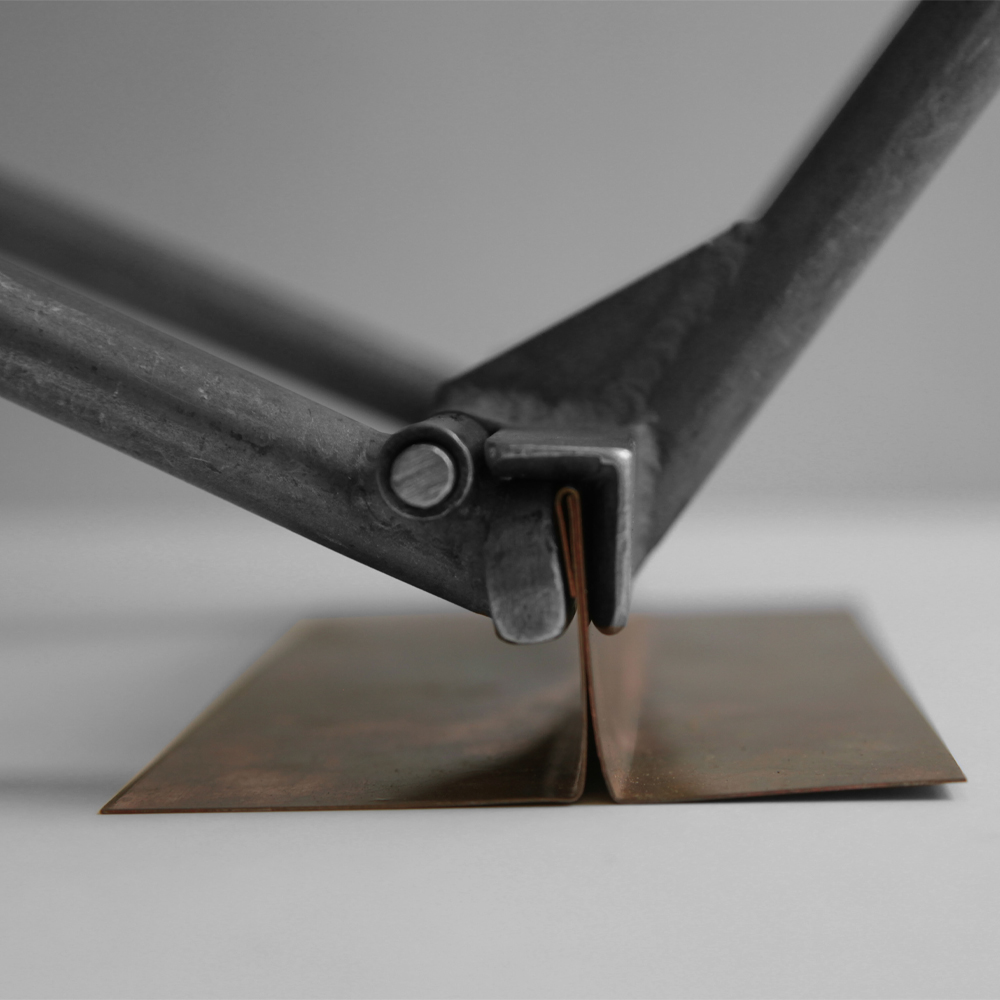
The aim for this test was to see: how well each seam performed structurally, how practical it would be to create these seams on the complex structure, as well as to examine if it were possible to have a water tight structure. The best seam structurally and practically considering the tools available was the overlapping seam with periodic pop rivets. To make a water tight structure was impossible with the tools we had alone, as the copper strip vertices would warp during the incremental forming process, revealing gaps for water to pass through. Making the corners overlap was also impossible, as the small section would have to be at a minimum triply curvature for it to work. This precision cannot be achieved with the tools or materials available.
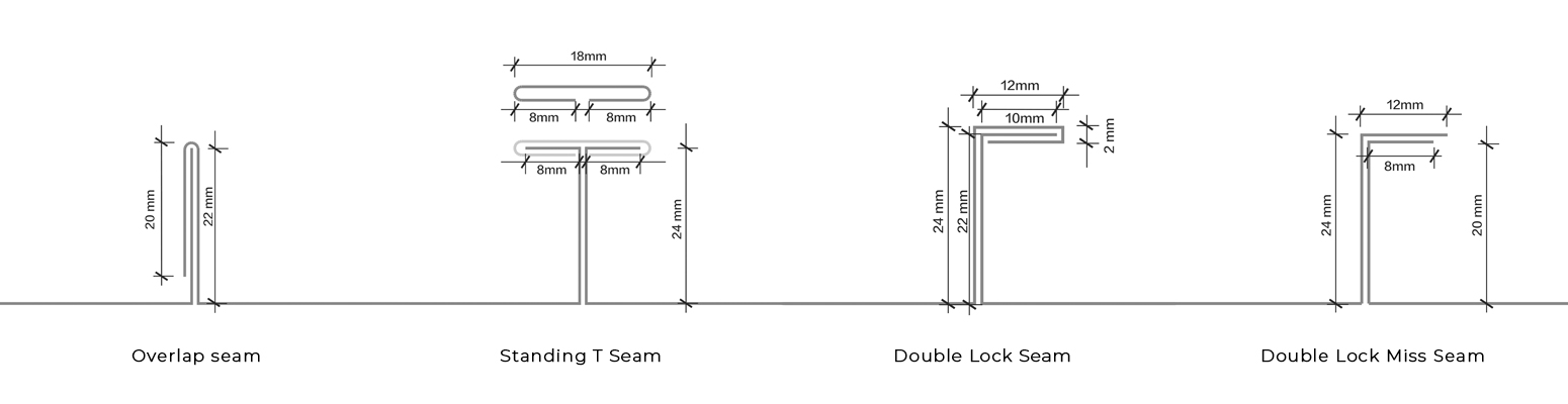
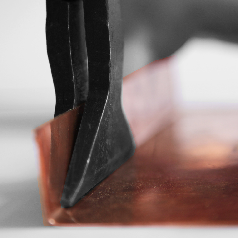
Forming an Overlapping Seam using a Seaming Tongs
Forming an Overlapping Seam using a Mechanical Lock Seamer
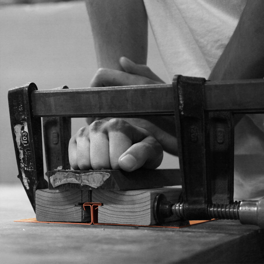
Forming Standing T Seams using timber jigs with clamps
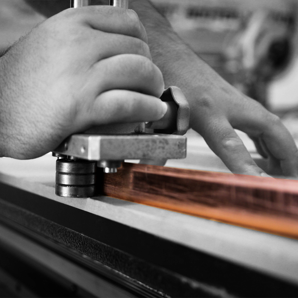
Forming Double Lock Seams using Edge Rollers
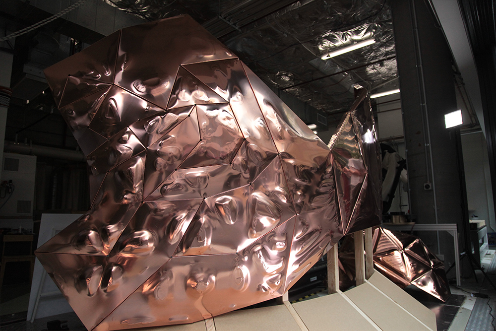
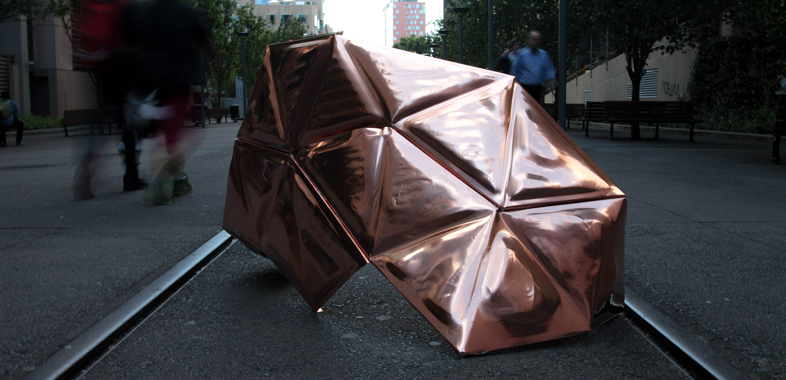
Scale Prototype
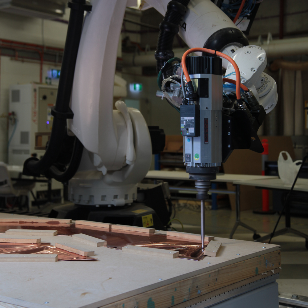
KUKA Robotic Arm fabricating copper sheet
Result of fabricating single copper strip
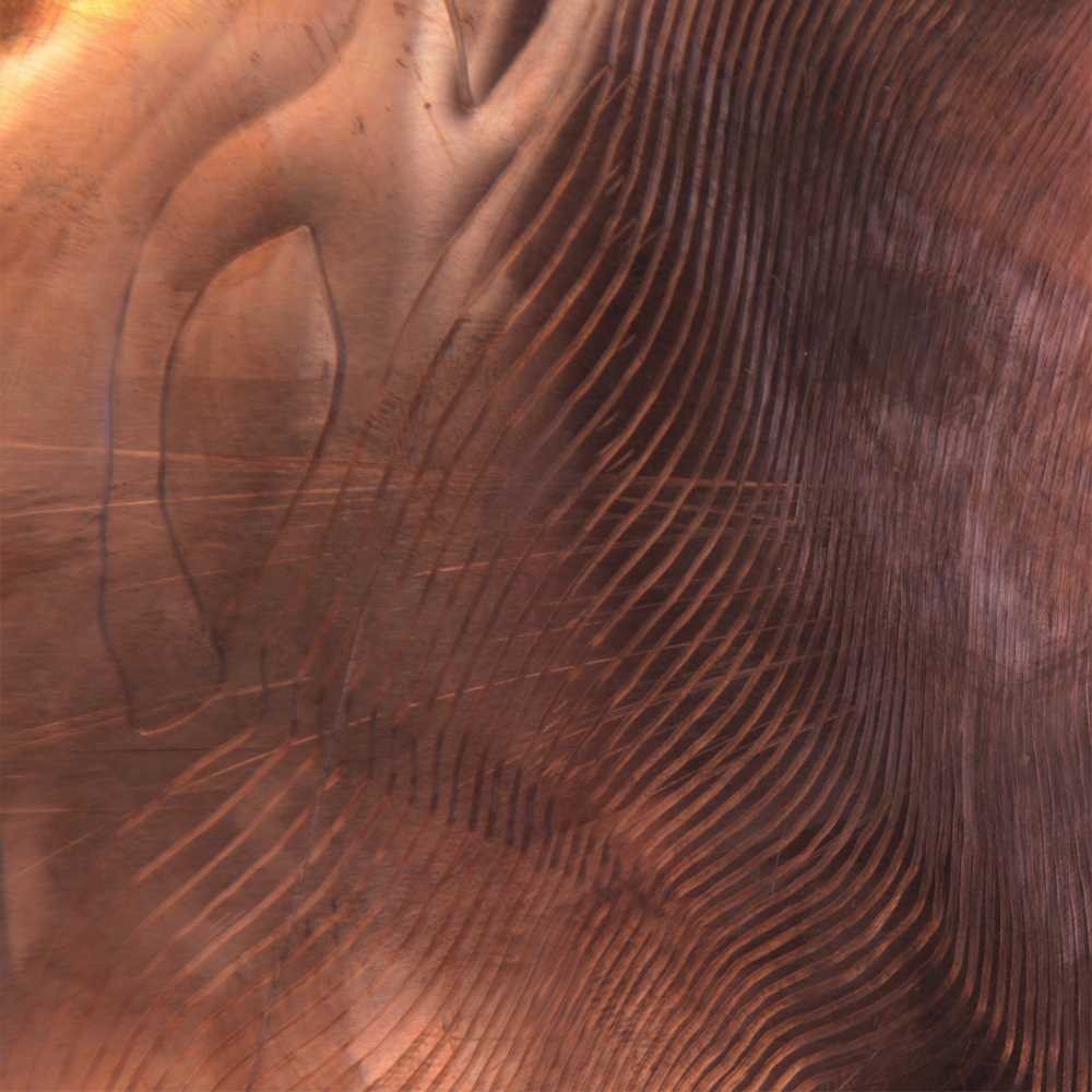
Incremental Forming toolpath details
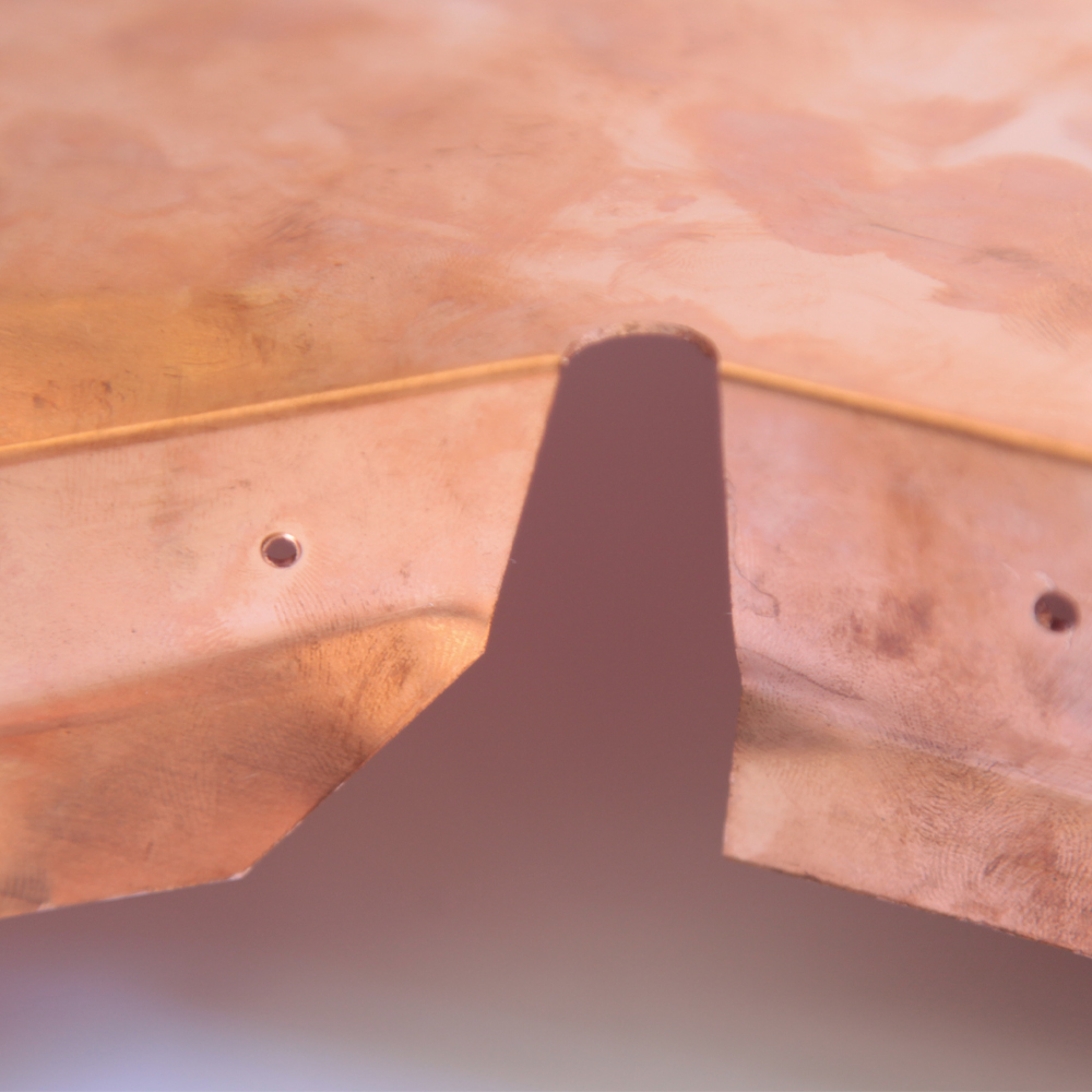
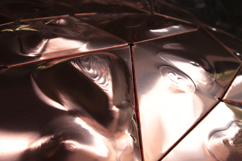
Vertex Detail pre-seaming
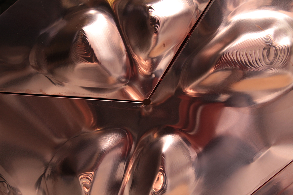
Final Facade Detail
Vertex Detail pre-seaming
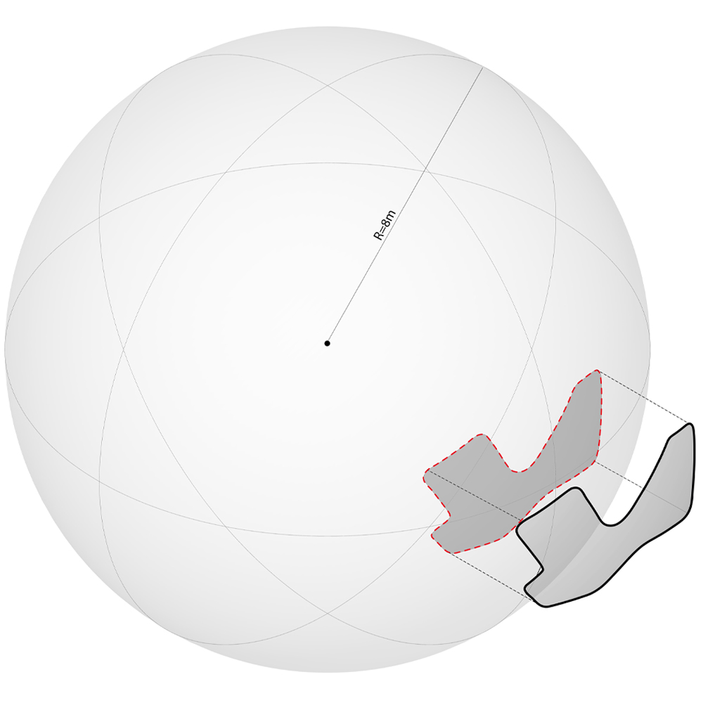
Macro
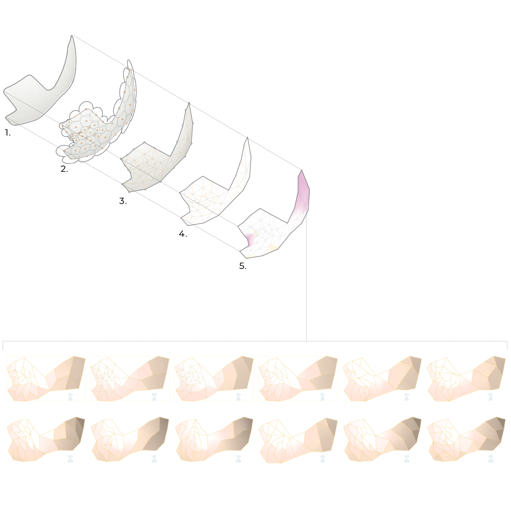
Meso
1. Base Surface - Global Form
2. Circle Packing - Equalised point along surface
3. Mesh Creation - Delaunay triangulationof discrete point set
4. Discretisation of Form - Creating strip panels of 3D form
5. Panel Utilisation Analysis
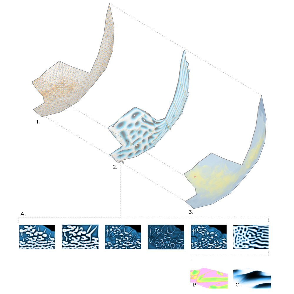
Micro
1. Subdivision of Surfaces
2. Scalar Deformation
3. Bending Energy Analysis
A. Scalar Patternation
B. Material Thickness Analysis
C. Surface Deformation
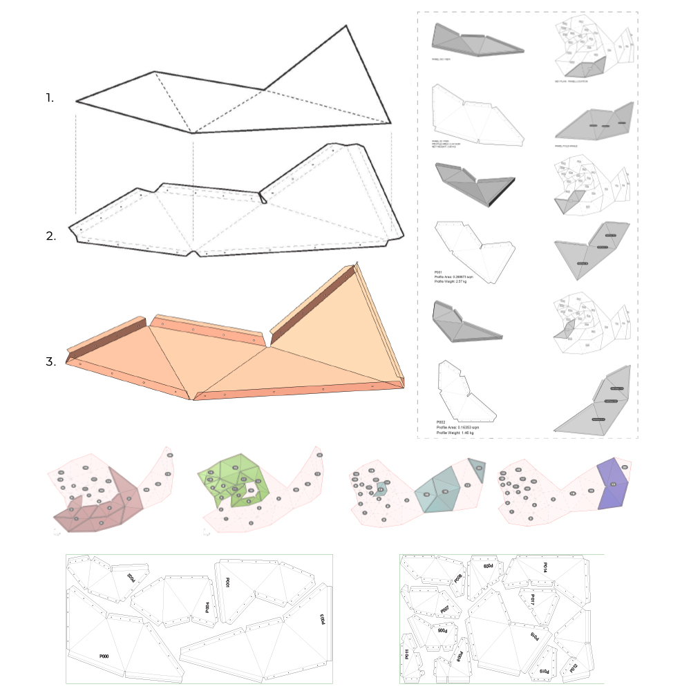
Fabrication Process
1. Inital Surface
2. CNC Cutting Sheet
3. Folded Sheet
Final Facade Outcome